translate

Showing posts with label sedimentologi. Show all posts

February 12, 2012

Sedimentology : Contour Currents

Density differences in surface ocean water caused by temperature or salinity variations create vertical circulation of water masses in the ocean commonly referred to as thermohaline circulation. Circulation is initiated primarily at high latitudes as cold surface waters sink toward the bottom, forming deep-water masses that flow along the ocean floor as bottom currents. The path of these bottom currents is influenced by the position of oceanic ridges and rises and other topographic features such as narrow passages through fracture zones. Owing to density stratification of ocean water, bottom currents adjacent to continental margins tend to flow parallel to depth contours or isobaths and thus are often called contour currents.

The movement of these currents is also affected by the Coriolis force, which likewise tends to deflect them (left in the Southern Hemisphere and right in the Northern Hemisphere) into paths parallel to depth contours; thus, they are sometimes also called geostrophic contour currents.

In the modem ocean, Antarctic bottom water runs down the continental slope, circulates eastward around the Antarctic continent possibly several times, and then flows northward into the Atlantic, Indian, and Pacific oceans (Stow, 1994). In the North Atlantic, deep bottom water flows south out of the Norwegian Greenland seas, Labrador Sea, and other parts of the North Atlantic. Interaction of these deep-water masses creates a highly complex ocean circulation system.

Because contour currents are best developed in areas of steep topography where the bottom topography extends through the greatest thickness of stratified water column (Kennett, 1982), they are particularly important on the continental slope and rise. Photographs of the deep seafloor have revealed current ripples in some areas and suspended sediment clouds and seafloor erosional features in others, both of which suggest that some contour currents can achieve velocities on or near the seafloor great enough to erode the seabed and transport sediment. Evidence is now available (e.g., Hollister and Nowell, 1991) which suggests that the speed of these bottom currents may be accelerated in some parts of the ocean to velocities on the order of 40 em/ s, perhaps because of the superimposed influence of large-scale, wind-driven circulation at the ocean's surface. That is, eddy kinetic energy may be transmitted from the surface of the ocean to the deep seafloor. Intensification may also occur where the Coriolis Force causes deep flows to bank up against the continental slope on the westem margins of ocean basins, where it is unable to move upslope against gravity and thus becomes restricted and intensified (Stow, 1994). Where bottom currents are intensified, resulting motions near the seafloor are so energetic that they have been referred to as "abyssal storms" or "benthic storms" (Hollister and Nowell, 1991), particularly because huge amounts of fine sediments are stirred up and transported by these energetic pulses. Contour currents are believed to have had a particularly important role in shaping and modifying continental rises, such as those off the eastern coast of North America.


Refference : Boggs Jr, Sam. 2006. Principles Of Sedimentology And Stratigraphy 4th Edition. Pearson Education, Inc. New Jersey.

January 14, 2012

Free download Ebook | Facies Model : a Response to sea level change by Walker and James

Free download Ebook | Facies Model : a Response to sea level change by Walker and James

It can be downloaded HERE


KEYWORDS : Facies model ebook, facies model, facies model

Free download e-journal : The Petroleum System: From Source to Trap (AAPG Memoir No. 60) by Lagoon & Dow

Free download e-journal : The Petroleum System: From Source to Trap (AAPG Memoir No. 60) by Lagoon & Dow

It can be downloaded HERE
Archive Password : ebooksclub.org


Keywords :  The Petroleum System: From Source to Trap (AAPG Memoir No. 60) by Lagoon & Dow, AAPG Memoir 60, Forearc basin, accretionary prism. 

Free Download E-journal : Fine-Grained Turbidite Systems (AAPG Memoir vol. 72)

Free Download E-journal : Fine-Grained Turbidite Systems (AAPG Memoir vol. 72) by Bouma & Stone

It can be downloaded HERE


Keywords : Free Download E-journal : Fine-Grained Turbidite Systems (AAPG Memoir vol. 72), AAPG MEMOIR 72, Turbidite system Bouma, Turbidite AAPG MEMOIR

January 13, 2012

Free download Ebook | Sedimentary Basins : Evolution, Facies, and Sediment Budget by Einsele Gerhard

Free download Ebook | Sedimentary Basins : Evolution, Facies, and Sediment Budget by Einsele Gerhard

It can be downloaded HERE.
Archive Password : ebooksclub.org


keywords : einsele gerhard, sedimentary basins, forearc basins, free download ebook sedimentary basins

January 7, 2012

Websites : Organizations or Societies Promoting Sedimentology and Stratigraphy

American Association Petroleum Geologists (AAPG)
http:// www.aapg.org/ - Student Chapter http://ugmsc.wordpress.com

American Geological Institute
http://www.agiweb.org/

American Petroleum Institute
http://api-ec.api.org/newsplashpage/index.cfm

Canadian Society of Petroleum Geologists
http://www.cspg.org/

Clay Mineral Society
http://cms.lanl.gov/

Geological Association of Canada
http://www.esd.mun.ca/-gac/ ABOUT /presenti.html

Geological Society of America
http://www.geosociety.org/pubs/index.htm

Index of U.S. Geological Survey Web Sites
http://www.usgs.gov/network/

International Association of Sedimentologists (lAS)
http://www.iasnet.org/publications/index.asp

International Union of Geological Sciences (lUGS)
http://www.iugs.org/ See also lugs Links to lugs Bodies
http://www.iugs.org/iugs/links.htm

North American Commission on Stratigraphic Nomenclature
http://www.agiweb.org/nacsn/

Paleontological Society
http://www.paleosoc.org/

Society for Sedimentary Geology (SEPM)
http://www.sepm.org/

Soil Science Society of America
http://www.soils.org/


Refference : Boggs Jr, Sam. 2006. Principles Of Sedimentology And Stratigraphy 4th Edition. Pearson Education, Inc. New Jersey.

December 24, 2011

SEDIMENTARY BASINS and THEIR TECTONIC SETTINGS

We now recognize that the origin of sedimentary basins is related in some way to
crustal movements and plate-tectonics processes.

Tectonic Settings

Divergent Settings


Terrestrial rift valleys : Rifts within continental crust commonly associated with
bimodal volcanism.
Modern example: Rio Grand Rift (New Mexico).

Proto-oceanic rift troughs : Incipient oceanic basins floored by new oceanic crust and flanked by young rifted continental margins.
Modern example: Red Sea.


Intraplate Settings

Continental rises and terraces : Mature rifted continental margins in intraplate settings
at continental-oceanic interfaces.
Modern example: East coast of USA.

Continental embankments : Progradational sediment wedges constructed off edges
of rifted continental margins.
Modern example: Mississippi Gulf Coast.

Intracratonic basins : Broad cratonic basins floored by fossil rifts in axial zones.
Modern example: Chad Basin (Africa).

Continental platforms : Stable cratons covered with thin and laterally extensive sedimentary strata.
Modern example: Barents Sea (Asia)
.
Active ocean basins: Basins floored by oceanic crust formed at divergent plate
boundaries unrelated to arc-trench systems (spreading still active).
Modern example: Pacific Ocean.

Oceanic islands, aseismic ridges and plateaus: Sedimentary aprons and platforms formed in
intraoceanic settings other than magmatic arcs.
Modem example: Emperor-Hawaii seamounts

Dormant ocean basins: Basins floored b y oceanic crust, which i s neither spreading nor subducting (no active plate boundaries within or adjoining basin).
Modem example: Gulf of Mexico.


Convergent Settings

Trenches: Deep troughs formed by subduction of oceanic lithosphere.
Modem example: Chile Trench.

Trench-slope basins: Local structural depressions developed on subduction complexes.
Modem example: Central America Trench.

Fore-arc basins: Basins within arc-trench gaps.
Modern example: Sumatra.

 Intra-arc basins : Basins along arc platform, which includes superposed
and overlapping volcanoes.
Modern example: Lago de Nicaragua.

Back-arc basins: Oceanic basins behind intraoceanic magmatic arcs
(including interarc basins between active and remnant
arcs), and continental basins behind continental-margin
magmatic arcs without foreland fold-thrust belts.
Modern example: Marianas.

Retro-arc foreland basins: Foreland basins on continental sides of continental-margin arc-trench systems (formed by subduction-generated compression and/ or collision).
Modern example: Andes foothills.

Remnant ocean basins: Shrinking ocean basins caught between colliding continental margins and/ or arc-trench systems, and ultimately subducted or deformed within suture belts.
Modern example: Bay of Bengal.

Peripheral foreland basins: Foreland basins above rifted continental margins that have been pulled into subduction zones during crustal collisions (primary type of collision-related forelands).
Modern example: Persian Gulf.

Piggyback basins: Basins formed and carried atop moving thrust sheets.
Modern example: Peshawar Basin (Pakistan).

 Foreland intermontane basins : (broken forelands): Basins formed among basement-cored uplifts in foreland settings. Modern example: Sierras Pampeanas basins (Argentina).


Transform Settings


Transtensional basins: Basins formed by extension along strike-slip fault systems.
Modern example: Salton Sea (California).

Transpressional basins: Basins formed by compression along strike-slip fault systems.
Modern example: Santa Barbara Basin (California) (foreland).

Transrotational basins: Basins formed by rotation of crustal blocks about vertical axes within strike-slip fault systems.
Modern example: Western Aleutian fore-arc (?).


Hybrid Settings

Intracontinental wrench basins: Diverse basins formed within and on continental crust owing to distant collisional processes.
Modern example: Quaidam Basin (China).

Aulacogens: Former failed rifts at high angles to continental margins, which have been reactivated during convergent tectonics, so that they are at high angles to orogenic belts.
Modern example: Mississippi Embayment.


Impactogens: Rifts formed at high angles to orogenic belts, without preorogenic history (in contrast with aulacogens).
Modern example: Baikal Rift (Siberia) (distal).

Successor basins: Basins formed in intermontane following cessation of local orogenic or taphrogenic activity.
Modern example: Southern Basin and Range (Arizona).


Keywords : basins, sedimentary basins, basin classification, tectonic basin, rift, compressional basin


Refference : Boggs Jr, Sam. 2006. Principles Of Sedimentology And Stratigraphy 4th Edition. Pearson Education, Inc. New Jersey.

December 23, 2011

Neutron Log & Density Log

Neutron Log & Density Log


Neutron logs are logs that are used to measure the hydrogen index contained in the rock formation. Hydrogen index is the ratio of the concentration of hydrogen atoms / cm cubic of rock on the content of pure water at 75 F. Neutron log is not really measure the porosity, but measure the hydrogen index in the pores of rocks.

The more porous rock, the more higher the hydrogen content and hydrogen index. Thus, rocks that contain lots of hydrogen can be interpreted to have high porosity as well. In practice the interpretation of porosity can be done with collaboration of neutron log with density log.

Density logging was conducted to measure the density of the rock along the borehole. Density is measured  the overall density of the rock matrix and the fluid contained in the pore. The working principle of the tool is the emission of radioactive sources. The more dense rocks the more harder radioactive rays and fewer emissions of radioactive emissions are calculated by the receiver (counter).

https://blogger.googleusercontent.com/img/b/R29vZ2xl/AVvXsEgymbiE2dhBsBy_RGZR8rZdtf4as8MJ0CWg-A8w-YyaBKRBHkpMu7Whatpy3uUyfmma5DQyCBF65xemP0Qzkv-VBZdW6nBNyEeZokRYWbKl5sGcU4irAD3MIGQqt_Eu4xsgifrfx8FKPJH3/s400/

Merging neutron porosity log and density porosity log are very useful for detecting gas in the reservoir zone. Gas zones are indicated by 'cross-over' between the neutron and density logs.

 In the picture above looks at the reservoir zone (low gamma ray), there is a 'cross-over' between the density and neutron. , in this case the neutron porosity lower than the density porosity.

Keywords: neutron log, density log, density log, well log, log, Neutron Log & Density Log

Reference:
John T. Dewan, "Open-Hole Nuclear Logging - State of the Art" - SPWLA Twenty-Seventh Annual Logging Symposium, June 9-13 1986.
http://ensiklopediseismik.blogspot.com/2009/02/neutron-porosity-dan-density-logging.html
Surjono, S.S., Sarju Winardi., D.H.Amijaya.2010. Analisis Sedimentologi, Pustaka Geo, Yogyakarta
Harsono, Adi. 1994. Pengantar Evaluasi Log. Schlumberger. Jakarta

December 22, 2011

Log Neutron & Log Densitas

Log Neutron adalah log yang digunakan untuk mengukur indeks hidrogen yang terdapat pada formasi batuan.  Indeks hidrogen adalah rasio dari konsentrasi atom hydrogen/cm kubik batuan terhadap kandungan air murni pada suhu 75 F. Log Neutron sebenarnya bukan mengukur porositas, tapi mengukur indeks hidrogen pada pori-pori batuan.

Semakin berpori batuan maka semakin banyak kandungan hidrogen dan semakin tinggi indeks hidrogen. Sehingga, batuan yang banyak mengandung hidrogen dapat ditafsirkan memiliki porositas yang tinggi pula.  Pada praktiknya interpretasi porositas dapat dilakukan dengan mengolaborasikan log neutron dengan log densitas.

Density logging sendiri dilakukan untuk mengukur densitas batuan disepanjang lubang bor,. Densitas yang diukur adalah densitas keseluruhan dari matriks batuan dan fluida yang terdapat pada pori. Prinsip kerja alatnya adalah dengan emisi sumber radioaktif. Semakin padat batuan semakin sulit sinar radioaktif tersebut ter-emisi dan semakin sedikit emisi radioaktif yang terhitung oleh penerima (counter).

Penggabungan neutron porosity dan density porosity log sangat bermanfaat untuk mendeteksi zona gas dalam reservoir. Zona gas ditunjukkan dengan ‘cross-over’ antara log neutron dan density.

https://blogger.googleusercontent.com/img/b/R29vZ2xl/AVvXsEgymbiE2dhBsBy_RGZR8rZdtf4as8MJ0CWg-A8w-YyaBKRBHkpMu7Whatpy3uUyfmma5DQyCBF65xemP0Qzkv-VBZdW6nBNyEeZokRYWbKl5sGcU4irAD3MIGQqt_Eu4xsgifrfx8FKPJH3/s400/density2.jpg

Pada gambar di atas terlihat pada zona reservoir (low gamma ray), terdapat ‘cross-over’ antara density dan neutron., dalam hal ini neutron porosity lebih rendah dari density porosity.


Keywords : Log neutron, Log densitas, Log density, Log sumur, log

Reference:
John T. Dewan, "Open-Hole Nuclear Logging - State of the Art" - SPWLA Twenty-Seventh Annual Logging Symposium, June 9-13 1986.
http://ensiklopediseismik.blogspot.com/2009/02/neutron-porosity-dan-density-logging.html
Surjono, S.S., Sarju Winardi., D.H.Amijaya.2010. Analisis Sedimentologi, Pustaka Geo, Yogyakarta
Harsono, Adi. 1994. Pengantar Evaluasi Log. Schlumberger. Jakarta

December 18, 2011

Log Resistivitas (Resistivity log)

Log Resistivitas (Resistivity Log) adalah log yang digunakan untuk mengukur sifat batuan dan fluida pori  (minyak, gas, air)  disepanjang lubang bor dengan mengukur sifat tahanan kelistrikannya. Resistivitas berbanding terbalik dengan konduktivitas.

Besaran pada log resistivitas batuan menggunakan satuan Ohm. Jika batuan mengandung fluida seperti air formasi yang sifatnya salin, maka  kurva resistivitasnya akan menunjukkan angka yang sangat rendah karena sifat air yang salin cenderung bersifat konduktif (kebalikan dari resistif). Dan pada minyak atau gas, kurva resistivitas akan menunjukkan angka yang sangat tinggi karena minyak atau gas cenderung memiliki hambatan yang sangat tinggi.

 Log resistivitas bermanfaat sekali dalam evaluasi formasi khususnya untuk menganalisa apakah suatu reservoir mengandung air garam (wet) atau mengandung hidrokarbon, sehingga log ini digunakan untuk menganalisis Hidrocarbon-Water Contact.

Contoh Gambar ilustrasi Log Resistivitas (kontak hidrokarbon-air)


https://blogger.googleusercontent.com/img/b/R29vZ2xl/AVvXsEhahkFPpHYgJE-jWkJ7xKBiZuHtU0lAAQyql-Pcvg4lbP6c1F572efoytdVTmX0c_vI_njZwBwr4O9nZvu81SR1SRk0d6Dieas_zSKs0i8qA9EzwTuRG0_h6THU94xAhwElNCcDMmWI7iS9/s400/res1.jpg

Didalam pengukuran resistivity log, biasanya terdapat tiga jenis ‘penetrasi’ resistivity, yakni shallow (borehole), medium (invaded zone) dan deep (virgin) penetration. Perbedaan kedalaman penetrasi ini dimaksudkan untuk menghindari salah tafsir pada pembacaan log resistivity karena mud invasion (efek lumpur pengeboran) dan bahkan dapat mempelajari sifat mobilitas minyak.

Resistivity log memiliki kegunaan lain yakni untuk mendeterminasi tingkat saturasi air (Water Saturation). Semakin tinggi saturasi air maka resistivity akan semakin rendah. Prediksi Water Saturation dari Resistivity log dapat dilakukan dengan berbagai algoritma diantaranya dengan Persamaan Archie


Sumber : Surjono, S.S., Sarju Winardi., D.H.Amijaya.2010. Analisis Sedimentologi, Pustaka Geo, Yogyakarta
 http://ensiklopediseismik.blogspot.com

December 17, 2011

Log Sinar Gamma (Gamma Ray Log)

Log Sinar Gamma atau Gamma Ray Log adalah log yang digunakan untuk mengukur tingkat radioaktivitas suatu batuan. Radioaktivitas tersebut disebabkan karena adanya unsur Uraniun, Thorium, Kalium pada batuan. Log ini biasa dipakai di industri perminyakan pada saat eksplorasi migas.

Unsur radioaktif biasanya banyak terdapat dalam shale karena shale merupakan batuan yang terendapkan paling akhir. Selain itu kadar radioaktif juga tinggi pada abu vulkanik (volcanic ash), tuff, hasil pelapukan granit, dan garam radioaktif yang terlarut dalam air formasi yang mengisi pori-pori batuan.. Selain itu, batuan beku umumnya mempunyai radioaktif yang tinggi. Pada batupasir / sandstone juga ditemui unsur radioaktif, namun sangat sedikit sekali jumlahnya.

Fungsi Log gamma ray yaitu untuk mendeteksi adanya lapisan shale dibawah permukaan bumi, dan juga lapisan batupasir berdasarkan kandungan radioaktif unsur-unsur K,U,Th,dan lain-lain. Log Gamma ray ini perlu dilengkapi dengan log lainnya seperti log SP, log resistivity, log neutron-density, dll agar tidak terjadi kesalahan interpretasi batuan. Contohnya intrusi batuan beku dengan shale.

Jika kita berekerja di sebuah cekungan dengan lingkungan pengendapan fluvio-deltaic atau channel system dimana biasanya sistem perlapisannya terdiri dari sandstone atau shale (sand-shale interbeds), maka log gamma ray ini akan sangat membantu didalam evaluasi formasi (Formation Evaluation- FE).

Seperti halnya logging yang lainnya, pengukuran gamma ray log dilakukan dengan menurunkan instrument gamma ray log kedalam lubang bor dan merekam radiasi sinar gamma untuk setiap interval tertentu. Biasanya interval perekaman gamma ray (baca: resolusi vertikal) sebesar 0.5 feet.

Dikarenakan sinar gamma dapat menembus logam dan semen, maka logging gamma ray dapat dilakukan pada lubang bor yang telah dipasang casing ataupun telah dilakukan cementing. Walaupun terjadi atenuasi sinar gamma karena casing dan semen, akan tetapi energinya masih cukup kuat untuk mengukur sifat radiasi gamma pada formasi batuan disampingnya.

Seperti yang disebutkan diatas bahwa gammar ray log mengukur radiasi gamma yang dihasilkan oleh unsur-unsur radio aktif seperti Uranium, Thorium, Potassium dan Radium. Dengan demikian besaran gamma ray log yang terdapat didalam rekaman merupakan jumlah total dari radiasi yang dihasilkan oleh semua unsur radioaktif yang ada di dalam batuan. Untuk memisahkan jenis-jenis bahan radioaktif yang berpengaruh pada bacaan gamma ray dilakukan gamma ray spectroscopy. Karena pada hakikatnya besarnya energy dan intensitas setiap material radioaktif tersebut berbeda-beda.

Spectroscopy ini penting dilakukan ketika kita berhadapan dengan batuan non-shale yang memungkinkan untuk memiliki unsur radioaktif, seperti mineralisasi uranium pada sandstone, potassium feldsfar atau uranium yang mungkin terdapat pada coal dan dolomite.

Gamma ray log memiliki satuan API (American Petroleum Institute), dimana tipikal kisaran API biasanya berkisar antara 0 s/d 150. Walaupun terdapat juga suatu kasus dengan nilai gamma ray sampai 200 API untuk jenis organic rich shale.

Gambar Log Gamma Ray (warna Merah)


http://www.spec2000.net/text100fp/image035.jpg


Sumber : Surjono, S.S., Sarju Winardi., D.H.Amijaya.2010. Analisis Sedimentologi, Pustaka Geo, Yogyakarta
http://ensiklopediseismik.blogspot.com/2009/01/gamma-ray-log.html

December 5, 2011

Sedimentary Structure

Sedimentary Structures

Sediment is a dynamic data structure that is very useful to identify the deposition environment. The structure of the sediment by physical processes before, during and after sedimentation.
The process is caused among others by:
a. Fluid Flow
b. The mass flow
c. Transportation by agents of erosion (wind, snow)
d. The process of biogenic
e. The process of chemical
f. The process of physics
Sedimentary structures reflect environmental conditions during sedimentation and control changes, and since that's sedimentary structures have many uses, among others, namely:
a. Interpretation of the deposition environment (transport mechanism, the direction of flow, depth, wind power & speed relative currents, tectonic sedimentation, and the condition of environment itself.)
b. Determine the top and bottom layers deported.
c. Determine paleogeography and early flows of an area.

Structural Classification of Sediments
1. Structure of erosion: is a structure formed by erosion caused by fluid flow and stream sediments prior to deposition above the plane of the layers. This type of erosion structures such as sole marks (flute casts, groove casts) and channels and scours.
a. Sole Mark: The structure of the sediment found on the top or bottom of a layer (Boggs, 1992)
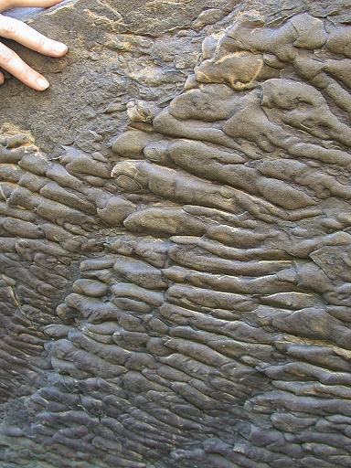
Positive mold shaped sandstone or more kasaryang rocks rest on a more subtle. Sole marks are usually found in sedimentary rocks that have undergone reversal

Figure 1: Sole marks are experiencing a reversal

Source : http://serc.carleton.edu/NAGTWorkshops/sedimentary/images/sole_marks.html

b. Flute cast: shaped like the sole mark the end like wildfire. Usually found in  turbiditic sandstones (Tucker, 1991)


figure2:

flute cast http://www.kueps.kyoto-u.ac.jp/ ~ web-bs/bs/gallery/flute_eg.html

c. groove cast: appears as a bulge rectilinear, rounded up sharply peaked, and lies in the field below the sandstone bedding. Some groove cast in groups and shows a set of protrusions and indentations that can be viewed as order-2 groove cast. Most of the set of order-2 groove cast showed divergent patterns and spread symmetrically on both sides of the main cast groove. The structure is thought to form due to the filling indentations formed in the mud hard by a moving object. The structure of such a structure also called shuffle ("drag mark"; "drag cast") (Kuenen, 1957). Groove casts generally appear in groups. More than one set of grooves cast is usually seen in the same plane, where the second set of cutting the first set with a taper angle cuts. Most of the set groove casts are usually eliminated by a second set of groove cast. In one set of groove cast, there would be little or perhaps no azimuth deviation. Groove cast rarely appear together with flute casts; both structures seem to be exclusive to one another. Individuals groove cast reliefs show only about 1 or 2 mm, very straight, and in most outcrops showed no starting point or end point. Therefore, we rarely find the "tools" are responsible for the formation of a groove cast. Groove cast should be distinguished from the structure of shear (slide mark; slide cast) formed by the movement of a large object or a mass of relatively large-sized objects, such as shale raft (shale raft). Mass tends to rotate shifts in both vertical and lateral direction so that the resultant curved traces and reflects the turn. Groove cast did not show such properties; groove marks are associated with other tools such as prod cast and skip casts. As flute casts, groove casts most commonly found in the field below turbidity bedding. Groove cast may be the type of structure under the bedding areas are most often found in Flysch facies.


The origins of groove cast has been a puzzle for some time. Groove cast is produced by the current structure. Cast groove orientation correlates very well with the current direction as indicated by other structures. In addition, evidence that the groove cast is a proven tool marks from the fact that very rarely found, namely the existence of particles of sand or fragments of the framework of the animals at the downstream end of the groove casts. However, the details of the dynamics of the formation of groove cast is still unclear. Most of the objects are transported by currents moving in a way rolling or bounced, as indicated by various types of collisions trail. Groove cast formation, on the other hand, requires a continuous contact between the "tool" with basic, even require the existence of pressure. In addition, as indicated by the groove ornate, "tool" that does not perform rotational movements. Eddy produces flute, not the groove. Thus, the mechanism of groove formation has not been fully understood. The existence of the sets intersecting groove cast is also a problem in itself. Assumed groove formed by turbid currents that move as a stream of concentrated toward the bottom of the slope. However, if a set of groove recording the movement to the bottom of the slope, then another set that will not record the movement toward the bottom of the slope. Because it is often found, the groove is one indicator of ancient currents that are very useful. However, the groove should be used in conjunction with other structures, groove only provide information about the azimuth, but did not provide information about the direction of flow.


d. Channels and scours: there are almost in all the environments of deposition. Appear as surface erosion at the base layer, and easily recognizable because it cuts the field of bedding. Rock is more rough than the surrounding rock. In a cross-channel structure found confusing possibilities.

2. Structure Deposition : syndepositional sedimentary structures, structures that are often encountered the bedding-lamination, cross maze, ripple waves, graded layer, a layer of massive, dune, antidune, etc.. To be described is the first structure 4.

a. bedding and lamination: by the horizontalitybedsets. Bedsets there are 2 that planar bedsets and composite bedsets.


Figure 3: sedimentary bedding


Sumber : http://ahmadsyarifhidayat.com/wp-content/uploads/2011/07/Picture2-300x195.jpg

b. The cross-bedding: bedding that indicates apparent angle between the layer =- internal boundary layer bedding. If the cross is a layer, called cross-bedding. When laminates, called cross lamination (Lewis and McConchie, 1994). There are two types of cross-bedding, which is planar and trough.


figure 4. Cross-bedding


Sumber: https://blogger.googleusercontent.com/img/b/R29vZ2xl/AVvXsEjsvengHfx2aXX_6cH8gpyn7ZTojLkzj-EwE1BWNVxzfpZepTGz9FCgE9oOqSlVGEFekSLC3INFip1eJuj7RO-lInq_jCSfUE1myC_vht4mNF1S4NDF31eOLtpRvq2YTaIZnAN8IbC1RdRj/s1600/Arahsimpangsiur.png


c. The gradation bedding: bedding that changing grain size gradation. If it is become fine upward, then it is called Normal grading. In contrast, when so-called inverse coarsening upward grading.


Figure 5: grade bedding


sumber: densowestliferz.wordpress.com

d. massive bedding: the bedding that does not indicate the presence of structures in the body is due to the massive bedding .deposition is so fast, debris result of high density sludge, or sediment gravity results


3. Structure of Post-Deposition
This structure is formed after the precipitation occurs, the result of the deformation process before it occurs compacting perfectly. Structures that formed were: slide and slump, convolute bedding, load casts, stylolite, sandstone dikes, dish and pillar and sheet dewatering.

a. Slide and slump : mass movements above the plane skidded along the slopes that cause little deformation on the sediment's body  (Tucker, 1991). Folds, faults and brecciation of the overall rise could occur in the slump. Slides will result in synsedimentary folds (Potter and Pettijohn, 1977). Movement slump will result in folds and faults.


figure 6.


sumber : discoveryofatlantis.ipower.com

Folds are irregularly shaped and spread in all directions is called convolute. This structure is located just above the plane bedding (Tucker, 1991). the genesis is uncertain, but may occur due to differences in vertical and lateral flow. crease yield and anticline Syncline, anticline usually used to detect hydrocarbon prospects.


b. Load cast : sole mark structures that occur as a result of loading and the difference between the density contrast. It usually occurs in the sandstone below the mudstone. Sandstone some will infiltrate into the mudstone due to loading.


figure 7.


source: geologyguobloki.blogspot.com

c. Dish and pillar: sedimentary structures are often found together. Dish (bowl) looks like a laminated thin and concave when viewed vertically. Pillar nearly equal to the dish, but this structure vertically cut sandstone layers (Boggs, 1992). Formed by the escape of water from the body of rock due to rapid deposition.


4. Structure of biogenic
Biogenic structures actually enter into the realm of ichnology (Collinson & Thompson, 1982). This structure can show the environment of deposition, sedimentation rates and processes (Compton, 1985)
Animals can leave traces in a way to touch, tread, move across, feeding on surface sediments, member / vent deposition of sediment in search of food, dig a hole to live and creates a shape after getting out of the hole sediments (Compton, 1985).

There are three aspects of the classification of trace fossils (Collinson & Thompson, 1982), namely:
a. Aspects of morphology: identification based on morphological and biological nomenclature according naming (ichnogenus and ichnospecies), reference is the size, way of life and preservation.
b. Aspects of preservation-Sedimentologists: morphological identification, model, positioning, and the preservation process.
c. Aspect-environmental way of life: by the way of life (cubichnia, repichnia, etc.)

Fossils can show the environment of deposition in addition it can be used to determine sedimentation whether or not to proceed. Fossils can also document the behavior of living things that have been extinct and also organisms that have no hard body parts. Moreover, it can indicate a direction of a layer.

5. Interpretation of the Ancient Flow
Sedimentary structures may show indications of an ancient stream, the paleoslope, direction / sediment dispersal patterns, full-circuit with the geometry of rock units and the location of sediment sources. The interpretation may also have economic significance, for example, to determine the spread of placer deposits (Graham, 1988)
Before performing the interpretation of an ancient stream, should be examined first supporting structure and the genesis of such structures. Besides the 3D cross-sectional layer of sediment must be known to be measured plunge, dip, strike, etc..
If the slope is less than 15 degrees and the rocks have not been deformed, it can be measured with a compass. If the slope is more than 15 degrees, may have been exposed to the geological structure, the structure must be identified first. Ancient flows can be determined through dip-strike, dip or plunge anyway.

6. Current Ripple Interpretation
Ripple and dune sand is coarse in appearance undulates-being. Usually generated by wind / water-offs. Ripple is less than 50cm in length and height from 0.5 to 3 cm, while the dune more than that (Collinson and Thompson, 1982)


gambar9.


http://www.brynmawr.edu/geology/314/fieldtrip04/fieldtrip04-Images/23.jpg


Bibliography
http://kepalabatu.finddiscussion.com/t8-belajar-terus
http://www.kueps.kyoto-u.ac.jp/~web-bs/bs/gallery/flute_eg.html
http://serc.carleton.edu/NAGTWorkshops/sedimentary/images/sole_marks.html
http://www.brynmawr.edu/geology/314/fieldtrip04/fieldtrip04-Images/23.jpg
http:// geologyguobloki.blogspot.com
http://discoveryofatlantis.ipower.com
http:// gemland.com
http:// densowestliferz.wordpress.com
Surjono, SS, Winardi, S., Amijaya, D, H, 2010, Analysis of Sedimentologists , Geo Books, London

December 3, 2011

Sedimentology in sedimentary basin : Fore-arc Basin

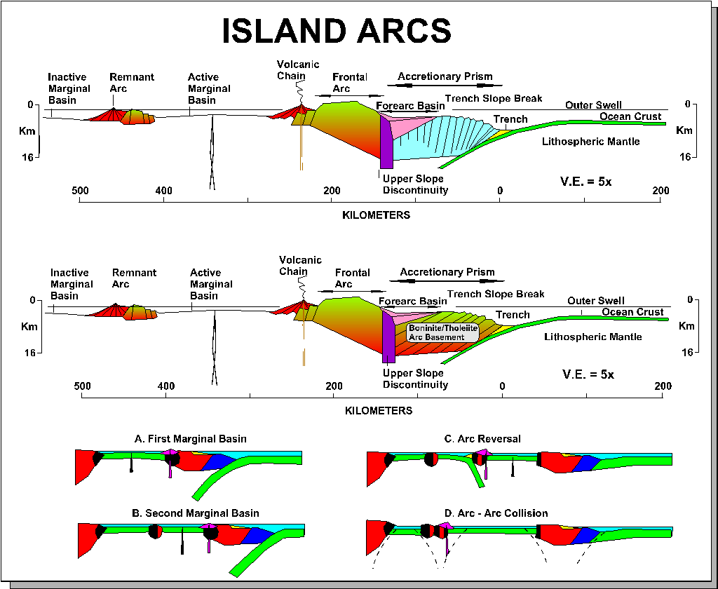
Along destructive margins, fore-arc refers to linear areas seaward of continental or oceanic volcanic arcs and landwards of any accretionary prism or trench .


A subsiding forearc referred to as a fore-arc basin, rooted in either modified continental or oceanic crust. Bathymetrically, fore-arcs are rather variable. Most are shelf-like, with gentle slopes up to 100 km or more wide. Some are much more complex, with a plethora of sub-basins and local uplifted highs associated  with both thrust and normal faulting. They act as sediment traps for the often prodigious sediment fluxes issuing from adjacent volcanic arcs. Volcanic airfalls, submarine slumps and eruption-driven  turbidity currents transfer sediment downlope. Floating pumice rafts disperse more widely over the destructive margin. The efficiency of the fore-arc trap increases as ridge-like barriers form by accretionary offscrapping at the trench-slope break. The tendency with time is for the initially  shallow fore-arc, with its coarse-grained basal deposits, to deepen quickly and then to infill gradually with a coarsening-upwards, predominantly turbiditic facies of arc volcanic provenance.

With time, the fore arc broadens and shallow by sediment onlap both oceanwards and landwards. The end result is an increasingly inefficient trap configuration. Basin fills from cainozoic and mesozoic example may reach up to 10km in thickness. The grat basin of california is perhaps the best exposed and investigated example of an ancient fore arc, whilst amongst active examples the sumatera-java fore-arc shows many classic features.

In order to understand how many fore arc basin originate as residual features superimposed upon older oceanic or continental-margin basement, it is necessary to conduct a thought experiment by imagining the likely sequence of events when subduction is initiated along a passive continental margin. During such a process, oceanic slab failure and reversely buoyant descent will occur oceanwards  of the last thinned  or modified continental crust. Fore-arcs are thus underlain by oceanic, modified oceanic or thinned continental crust, and bounded oceanwards by the first offscraped sediment of the nascent accretionary prism. Water depth are initially deep, liable to rapid infill by copious sediment flux from the adjacent arc.
Sediment loading induces extra flexural subsidence around the basin margin, causing forebulges, then waves of subsidence to migrate outwards towards both the trench-slope break and the volcanic arc, causing progressive onlap on those features. Fore-arc terrains along periodically extensional destructional margins undergo alternating uplift due to shortenng and subsidence as the area of the whole trench-arc gap episodically increases due to stretching.

Source : Leeder, Mike.1999.Sedimentology and Sedimentary Basins (From Turbulence to Tectonics). Blackwell Publishing. Malden (USA). page 520

keywords : Fore-arc basin, sedimentary basin, arc, sedimentology fore-arc

November 22, 2011

Basic of Evaluation Concepts : Properties of Rock for Log Analyzing


Logging provides data needed to evaluate the quantity of hydrocarbon in the coating on the actual situation.  Curves log provide data on the properties of rocks and fluids.

Rock properties that are important to analyze the logs are porosity, water saturation, permeability. The first two parameters can be calculated quantity of hydrocarbons in the layer, and the last parameter indicate where the hydrocarbon can be produced.

Porosity
Porosity is Part of the Total volume of porous rocks. In unconsolidated formation, number of porosity depends on grain size distribution. If all grain have a similar size, porosity will be able on number 0,35-0,4 (high). But, it will be lower if grains have variative size, because the small grain able to fill in space between larger grain.


Water Saturation
Water Saturation is Part of porous space filled with water (Sw). Residual part of water saturation named hydrocarbon saturation (Sh). Sh = 1 - Sw. The main purpose from logging operation is for this, make calculating saturation of water and hydrocarbon


Permeability
Permeability is ability of rocks to pass the fluids. Permeability depends on grain size of sedimentary rocks. Sediment with large grain size and large pore has high permeability number, and the opposite. 


Hydrocarbon-Bearing Rocks
Generally consist of sandstone, limestone, and dolomit.

Sand can moved and deposited by water. The more swift water flow, more coarse grain. Therefore the sand tends to have a similar porosity between of it's grains.

Limestone isn't like sand, it will be deposited by seawater movement. A few part solute deposit, and the other part is heaps of organic remains. Porosity of limestone is less similar than sandstone.

Dolomit is built when water rich of magnesium flow on limestone, and change few calcium with magnesium. Dolomitization is important mechanism to avail pore space for hydrocarbon accumulation.


Clays and Shales
Clays are main component of sedimentary rock. There are montmorillonite, illite, chlorite, and kaolinite.
Shales are composed from clays and silts ( soft silicates) that deposited by low energy sedimentation.
The permeability of shales is 0. Shales and Clays make Hydrocarbon Formation analyzing be difficult. You have to know log interpretation on clean formation, then analyzing dirty formation.


Article Basic of Evaluation Concepts : Properties of Rock for Log Analyzing is free in thi blog.
Source : Harsono,Adi.1994. Pengantar Evaluasi Log.

November 15, 2011

Log Evaluation : Preface

PREFACE

Measurement in well log can divided into 4 categories :

  1. Drilling Operation Log : mud logs, MWD (Measurement While Drilling), LWD (Logging While Drilling)
  2. Core Analyze
  3. Well log with wireline : electric, accoustic, radioactive, electromagnetic
  4. layer production test
Because of technically or economically, not all of measurements applicated in each well. For example, picking up core and LWD system need huge cost than others.

The main purpose of formation evaluation are :
  1. Identify reservoir
  2. Estimate hydrocarbon reserves
  3. Estimate hydrocarbon gains

LOGGING PROCESS

In exploration wells, It's important to gain information as much as possible continuously, in order to obtain a better observation of geological structure to correlating with the others well while oil field is on developing.

It's easily achieved with logging operation on openholes that started from maximum depth (TD) in to casing shoe. Do logging at short interval to avoid opennes formation layers toward mud system.

Logging operations have to done as fast as possible, but datas quality is more important. On final logging operation in Total Depth, important decisions will made based on logging, and it is determine the fate of well. And then you have to make some interpretations manually or with computer named Field Log Interpretation center (FLIC).

Log Evaluation : Preface - Source : Harsono, Adi. 1994. Pengantar Evaluasi Log. Jakarta

October 29, 2011

Kondisi Geologi Kali Boyong-Code


KONDISI GEOLOGI KALI BOYONG – KALI CODE

Kali Boyong dan Kali code merupakan Kali yang berada pada satu aliran. Mengalir dari hulu ke muara, hulunya berada di G.Merapi dan muaranya berada di Samudera Hindia. Nantinya aliran Kali code ini akan bertemu dengan Kali opak di daerah Imogiri. Semenjak letusan Merapi tahun 2010 lalu, terjadi perubahan signifikan terhadap provenance, stratigrafi, bahkan morfologinya. Hal ini diakibatkan banyaknya material erupsi Gunung merapi yang tertransport cukup jauh akibat curah hujan yang tinggi dan mengendapkan material-material volkaniklastik di sekitar Kali.

Kali Boyong
Kali Boyong merupakan hulu dari Kali Code, Kali boyong bercabang-cabang dan salah satu cabangnya adalah Kali Code. Pola aliran Kali boyong yaitu dendritik, karena merupakan ciri khas pola aliran sungai daerah bentang alam vulkanik. Kali Boyong merupakan Kali yang menjadi hulu dari Kali Code dan menjadi pemasok utama air yang melewati Kali Code. Kali Boyong mengalir dari lereng G.Merapi dan kemudian bercabang-cabang dan salah satu anak sungainya merupakan Kali Code. Bentuk lembah Kali Boyong berbentuk “U” sebagai salah satu akibat pengikisan oleh material vulkanik yang terbawa oleh air hujan. Kali boyong merupakan sungai berstadia muda.
Di Kali Boyong saat ini banyak sekali endapan-endapan hasil erupsi Gunung Merapi tahun 2010 lalu yang belum terkonsolidasi. Ini dimanfaatkan oleh para penambang pasir untuk mengeruk untung dari pasir merapi yang mempunyai nilai ekonomis untuk dijual sebagai bahan baku campuran dalam pembuatan konstruksi-konstruksi bangunan.


Gambar 1. Endapan material volkaniklastik pada dinding tepi Kali Boyong

Sebagai salah satu sungai yang membawa material erupsi merapi, di pinggir dinding Kali Boyong terdapat endapan-endapan sisa erupsi merapi pada beberapa tahun yang lalu. Dalam gambar terlihat material yang berukuran gravel – boulder berada diatas material yang jauh lebih halus. Hal ini disebabkan oleh material yang melewati sungai ini sangat pekat akan material erupsi sehingga batuan yang  jauh lebih besar bisa berada di bagian yang paling atas.
Secara stratigrafis Kali Boyong tersusun oleh {Wartono Rahardjo, dkk (1977), Wirahadikusumah (1989), dan Mac Donald dan Partners (1984)} :
-          Vulkanik Merapi Tua
Tersusun oleh breksi aglomerat dan juga lelehan lava yang mengandung olivine dan bertipe andesitik-basalt (Bemmelen, 1949).  Berumur pleistosen  (Wirahadikusumah, 1989) diukur dengan C-14

-          Vulkanik Merapi Muda
Tersusun atas rombakan merapi tua yang berupa endapan tuf, pasir, dan breksi yang terkonsolidasi sebagian dan masih lemah.


-          Formasi Sleman
Batuan penyusunnya berupa pasir dan kerikil diselingi bongkahan-bongkahan. Dari Utara ke selatan formasi ini semakin mengalami penebalan (Mac Donald and Partners, 1984).

-          Formasi Yogyakarta
Batuan yang menyusun formasi ini berupa perselingan pasir, kerikil, lanau dan lempung
(Mac Donald and Partners, 1984).
Provenance yang berada di Kali Boyong merupakan batuan hasil erupsi G. Merapi baik yang sudah terkonsolidasi ataupun masih berupa material sedimen. Material sedimen yang terdapat di Kali Boyong berukuran pasir –bongkah.

Kali Code
Kondisi Kali Code dewasa ini cukup memprihatinkan. Dimana terjadi banyak sekali hal-hal yang merusak keindahannya. Sebagai Contoh banyaknya masyarakat yang membuang sampah ke Kali Code. Hal ini merupakan pencemaran dan bisa berakibat buruk bagi ekosistem sungai. Belum lagi banyaknya masyarakat yang membuang limbah rumah tangga ke Kali Code.
Kali Code adalah anak Dari Kali Boyong yang mengalir di tengah kota Yogyakarta. Kali ini membelah kota Yogyakarta menjadi dua bagian. Stadia sungai ini termasuk dewasa jika dilihat dari bentuknya yang sudah meander dan lembahnya juga sudah berbentuk “U”. Air Kali Code biasa dimanfaatkan warga sebagai sumber air irigasi sawah/ladang. Di sekitar bantaran Kali Code juga dipakai untuk mendirikan pemukiman warga.
                Karena hulu dari Kali Code adalah Kali Boyong, maka setiap terjadi erupsi Gunung Merapi, Kali Boyong membawa material erupsi tersebut ke Kali Code. Seperti yang terjadi pada tahun 2010 lalu dimana Kali Code meluap akibat membawa banyak sekali material-material yang dihasilkan Gunung Merapi. Karena sering sekali membawa material erupsi Gunung Merapi maka di Kali Code pun terjadi pendangkalan dasar sungai yang berakibat tidak bisanya lagi Kali Code membawa debit air yang besar. Dan karena pendangkalan ini pula, kawasan sekitar Kali Code rawan terkena banjir lahar apabila terjadi erupsi seperti yang terjadi pada tahun 2010 lalu.
                Provenance dari Kali Code sendiri merupakan hasil dari material erupsi Gunung Merapi yang butirnya berukuran pasir – kerikil. Selain itu ditemukan pula batuan-batuan dari Formasi yang menyusun Kali Boyong, namun jumlahnya tidak banyak. Secara stratigrafis, Kali Code termasuk dalam cekungan Yogyakarta yaitu Formasi Sleman dan Formasi Yogyakarta, dan Kali Code merupakan hasil dari endapan Merapi muda (Wartono Rahardjo,1995).


Gambar 2. Kali Code saat terjadi banjir


                Kali Code pada akhirnya akan bertemu dengan aliran Kali Opak di daerah Imogiri. Dan selanjutnya sedimen – sedimen yang dibawa oleh aliran Kali Code akan diteruskan oleh Kali Opak menuju Samudera Hindia.

October 14, 2011

Struktur Sedimen


Struktur sedimen merupakan data dinamis yang sangat berguna untuk mengidentifikasi lingkungan pengendapan. Struktur sedimen oleh proses fisika sebelum,selama dan sesudah sedimentasi.
Proses tersebut disebabkan antara lain oleh :
a.      Arus fluida
b.      Aliran massa
c.       Transportasi oleh agen erosi (angin,salju)
d.      Proses biogenik
e.      Proses kimia
f.        Proses fisika
Struktur sedimen mencerminkan kondisi lingkungan saat sedimentasi dan perubahan-perubahan yang mengontrolnya, dank arena itulah struktur sedimen mempunyai banyak kegunaan, antara lain yaitu :
a.      Interpretasi lingkungan pengendapan ( mekanisme transport, arah aliran, kedalaman, kekuatan angin & kecepatan relative arus, tektonik sedimentasi, dankondisi lingkungannya itu sendiri.)
b.      Menentukan bagian atas dan bawah lapisan yang terdeportasi.
c.       Menentukan paleogeografi dan arus purba suatu daerah.

Klasifikasi Struktur Sedimen
1.      Struktur erosi : merupakan struktur  yang terbentuk akibat oleh erosi aliran fluida dan aliran sedimen sebelum pengendapan diatas bidang lapisan. Jenis struktur erosi antara lain sole mark (flute cast, groove cast) dan channels and scours.
a.      Sole Mark : Struktur sedimen yang terdapat pada bagian atas atau dasar suatu lapisan (Boggs, 1992)
Berbentuk cetakan positif pada batu pasir  atau yang lebih kasaryang menindih batuan yang lebih halus. Sole mark ini biasanya ditemui pada batuan sedimen yang telah mengalami pembalikan
Gambar 1 : Sole mark yang mengalami pembalikan

b.  Flute cast : berbentuk seperti sole mark yang ujungnya seperti jilatan api.  Biasanya ditemukan pada batupasir turbidit (Tucker,1991)


c.    groove cast : tampak sebagai tonjolan rektilinier, membundar hingga berpuncak tajam, serta terletak pada bidang perlapisan bawah batupasir. Sebagian groove cast berkelompok dan memperlihatkan adanya himpunan tonjolan dan lekukan yang dapat dipandang sebagai groove cast orde-2. Sebagian himpunan groove cast orde-2 itu memperlihatkan pola divergen dan tersebar secara simetris di kedua sisi groove cast utama. Struktur itu diperkirakan terbentuk akibat terjadinya pengisian lekukan-lekukan yang terbentuk pada lumpur keras oleh berbagai benda yang bergerak. Struktur seperti itu disebut juga struktur seretan (“drag mark”; “drag cast”) (Kuenen, 1957).

Groove cast umumnya muncul berkelompok. Lebih dari satu himpunan groove cast biasanya terlihat pada bidang yang sama, dimana himpunan kedua memotong himpunan pertama dengan sudut pemotongan yang lancip. Sebagian himpunan groove cast biasanya terhapuskan oleh himpunan groove cast kedua. Dalam satu himpunan groove cast, hanya akan ada sedikit bahkan mungkin tidak ada deviasi azimuth. Groove cast jarang muncul secara bersama-sama dengan flute cast; kedua struktur itu agaknya bersifat ekslusif satu terhadap yang lain. Individu-individu groove cast memperlihatkan relief hanya sekitar 1 atau 2 mm, sangat lurus, dan dalam kebanyakan singkapan tidak memperlihatkan titik awal maupun titik akhir. Karena itu, kita jarang menemukan “alat” yang bertanggungjawab terhadap pembentukan suatu groove cast.

Groove cast hendaknya dibedakan dari struktur geseran (slide mark; slide cast) yang terbentuk akibat bergeraknya suatu benda berukuran besar atau suatu massa benda berukuran relatif besar, misalnya rakit serpih (shale raft). Massa yang bergeser itu cenderung berputar baik pada arah vertikal maupun lateral sehingga jejak yang dihasilkannya melengkung dan mencermin-kan putaran itu. Groove cast tidak memperlihatkan sifat seperti itu; groove berasosiasi dengan tool mark lain seperti prod cast dan skip cast. Sebagaimana flute cast, groove cast paling sering ditemukan dalam bidang perlapisan bawah turbidit. Groove cast mungkin merupakan tipe struktur bidang perlapisan bawah yang paling sering ditemukan dalam fasies flysch.


Asal-usul groove cast telah menjadi teka-teki selama beberapa lama. Groove cast merupakan struktur yang dihasilkan oleh arus. Orientasi groove cast berkorelasi sangat baik dengan arah arus sebagaimana yang diindikasikan oleh struktur lain. Selain itu, bukti bahwa groove cast merupakan suatu tool mark terbukti dari fakta yang sangat jarang ditemukan, yaitu adanya partikel pasir atau fragmen rangka binatang pada ujung hilir dari groove cast. Walau demikian, detil-detil dinamika pembentukan groove cast masih belum jelas. Sebagian besar benda yang diangkut oleh arus bergerak dengan cara menggelundung atau melonjak-lonjak, sebagaimana yang diindikasikan oleh berbagai tipe jejak tumbukan. Pembentukan groove cast, di lain pihak, memerlukan adanya kontak menerus antara “alat” dengan dasar, bahkan memerlukan adanya tekanan. Selain itu, sebagaimana diindikasikan oleh groove berornamen, “alat” itu tidak melakukan pergerakan rotasional. Eddy menghasilkan flute, bukan groove. Dengan demikian, mekanisme pembentukan groove belum dipahami sepenuhnya.

Adanya himpunan-himpunan groove cast yang saling memotong juga merupakan sebuah masalah tersendiri. Groove diasumsikan terbentuk oleh arus turbid yang bergerak sebagai aliran pekat menuju bagian bawah lereng. Namun, jika suatu himpunan groove merekam pergerakan ke bagian bawah lereng, maka himpunan yang lain tidak akan merekam pergerakan ke arah bagian bawah lereng.
Karena sering ditemukan, groove merupakan salah satu indikator arus purba yang sangat bermanfaat. Walau demikian, groove hendaknya digunakan bersama-sama dengan struktur lain, groove hanya memberikan informasi mengenai azimuth, namun tidak memberikan informasi mengenai arah aliran.

d. Channels and scours : terdapat hamper di semua lingkungan pengendapan. Tampak sebagai permukaan erosi pada dasar lapisan, dan dikenali dengan mudah karena memotong bidang perlapisan. Batuannya lebih kasar disbanding batuan sekitarnya. Dalam suatu channel kemungkinan dijumpai struktur silang siur.

2.      Struktur Pengendapan : merupakan struktur sedimen syndepositional, struktur yang sering dijumpai yaitu perlapisan-laminasi, silang siur, gelembur gelombang, lapisan bergradasi,lapisan massif, dune, antidune, dll. Yang akan dijelaskan adalah 4 struktur pertama.

a.      Perlapisan dan laminasi : berdasarkan hokum horizontalitas, sedimen diendapkan secara horizontal danmembentuk lapisan-lapisan karena adanya perbedaan litologi. Struktur ini merupakan penciri dasar batuan sedimen. Perlapisan adalah lapisan sedimen yang ketebalannya diatas 1cm, sedangkan yang kurang dari 1cm adalah laminasi. Kumpulan lapisan datar yang mempunyai kesamaan karakteristik disebut bedsets. Bedsets ada 2 yaitu planar bedsets dan composite bedsets.

Gambar 3 : Perlapisan sedimen
Sumber : http://ahmadsyarifhidayat.com/wp-content/uploads/2011/07/Picture2-300x195.jpg

b.      Perlapisan silang : perlapisan yang menunjukkan adanya sudut yang jelas antara layer=-layer internal dengan bidang batas perlapisan. Apabila yang bersilang adalah lapisan, disebut cross-bedding. Bila laminasi, disebut cross lamination (Lewis and McConchie, 1994). Perlapisan silang ada 2 jenis, yaitu planar dan trough. 

gambar 4. Perlapisan silang
sumber : https://blogger.googleusercontent.com/img/b/R29vZ2xl/AVvXsEjsvengHfx2aXX_6cH8gpyn7ZTojLkzj-EwE1BWNVxzfpZepTGz9FCgE9oOqSlVGEFekSLC3INFip1eJuj7RO-lInq_jCSfUE1myC_vht4mNF1S4NDF31eOLtpRvq2YTaIZnAN8IbC1RdRj/s1600/Arahsimpangsiur.png


c.       Perlapisan gradasi : perlapisan yang ukuran butirnya berubah secara gradasi. Jika yang terjadi adalah menghalus ke atas, maka disebut nirmal grading. Sebaliknya, bila mengkasar ke atas disebut inverse grading. 


Gambar 5 : grade bedding
sumber: densowestliferz.wordpress.com
              
d.      Perlapisan massif : adalah perlapisan yang tidak menunjukkan adanya struktur dalam tubuh perlapisannya.Perlapisan ini terjadi akibat pengendapan yang begitu cepat, gelontoran hasil endapan densitas tinggi, atau endapan hasil gravitasi


3.     Struktur Pasca Pengendapan
Struktur ini terbentuk setelah pengendapan terjadi, hasil dari proses deformasi sebelum terjadi pembatuan secara sempurna. Struktur yang terbentuk antara lain yaitu : slide and slump, convolute bedding, load cast, stylolite, sandstone dykes, dish and pillar dan sheet dewatering.

a.      Slide and slump : gerakan massa diatas bidang gelincir disepanjang lereng yang menimbulkan sedikit deformasi pada tubuh sedimennya (Tucker, 1991). Lipatan, sesar naik dan breksiasi secara keseluruhan dapat terjadi pada proses slump. Slide akan menghasilkan lipatan synsedimentary(potter and Pettijohn, 1977). Gerakan slump akan menghasilkan lipatan dan patahan.


 gambar 6.
sumber : discoveryofatlantis.ipower.com

 Lipatan yang bentuknya tidak teratur dan menyebar ke segala arah disebut convolute. Struktur ini hanya terletak di atas bidang perlapisan (Tucker,1991). Genesanya belum dapat dipastikan, namun kemungkinan terjadi akibat perbedaan aliran secara vertical dan lateral. lipatan menghasilkan antiklin dan sinklin, biasanya antiklin dimanfaatkan untuk mendeteksi prospek hidrokarbon.


b.      Load cast : struktur sole mark yang terjadi akibat pembebanan dan perbedaan antara densitas yang kontras. Biasanya terjadi pada batupasir yang dibawahnya adalah batulumpur. Batu pasir sebagian akan menyusup ke dalam batulumpur akibat pembebanan.

 gambar 7.  sumber : geologyguobloki.blogspot.com

c.       Dish and pillar : struktur sedimen yang sering dijumpai secara bersama-sama. Dish (mangkok) terlihat seperti laminasi tipis dan cekung bila dilihat secara vertical. Pillar hamper sama dengan dish, namun struktur ini memotong lapisan batupasir secara vertikal (Boggs,1992). Terbentuk akibat lepasnya air dari tubuh batuan akibat pengendapan yang cepat.


4.    Struktur biogenik
Struktur biogenik sebenarnya masuk ke dalam ranah ichnology (Collinson & Thompson, 1982). Struktur ini dapat menunjukkan lingkungan pengendapan, tingkat dan proses sedimentasi (Compton, 1985)
Binatang dapat meninggalkan jejak dengan cara menyentuh, menapak, bergerak melintasi, makan pada permukaan sedimen, member/melubangi endapan sedimen untuk mencari  makanan, menggali lubang untuk hidup dan membentuk suatu bentukan setelah keluar dari lubang sedimen (Compton, 1985).

Terdapat 3 aspek klasifikasi fosil jejak (Collinson & Thompson, 1982), yaitu :
a.      Aspek morfologi : identifikasi berdasarkan morfologi  dan penamannya sesuai  nomenklatur biologis (ichnogenus dan ichnospecies), acuannya adalah ukuran, cara hidup dan preservasi.
b.      Aspek preservasi-sedimentologi: identifikasi morfologi, model, posisi, dan proses preservasi.
c.       Aspek cara hidup-lingkungan : berdasarkan cara hidup (cubichnia, repichnia, dll)

Fosil selain dapat menunjukkan lingkungan pengendapan ternyata dapat dipakai untuk mengetahui sedimentasi apakah berlanjut atau tidak. Fosil juga dapat mendokumentasikan perilaku makhluk hidup yang telah punah dan juga organism yang tidak mempunyai bagian tubuh yang keras. Selain itu dapat menunjukkan penunjuk arah atas suatu lapisan.

5.     Interpretasi Arus Purba
Struktur sedimen dapat menunjukkan indikasi arus purba, yaitu paleoslope, arah/pola penyebaran sedimen, hubungan arus purna dengan geometri satuan batuan dan lokasi sumber sedimen. Interpretasi tersebut juga dapat memiliki arti ekonomis, misalnya untuk mengetahui penyebaran placer deposit (Graham,1988)
Sebelum melakukan interpretasi arus purba, harus diteliti dahulu struktur yang menunjang dan genesa dari struktur tersebut. Selain itu penampang 3D lapisan sedimen harus diketahui untuk diukur plunge, dip, strike, dll.
Jika kemiringan kurang dari 15 derajat dan batuan belum mengalami deformasi, maka bisa diukur dengan kompas. Jika kemiringannya lebih dari 15 derajat, kemungkinan telah terkena struktur geologi, maka harus diidentifikasi dahulu strukturnya. Arus purba dapat ditentukan melalui dip-strike, atau pula dip-plunge.

6.     Interpretasi Current Ripple
              Ripple dan dune merupakan kenampakan undulasi pada pasir kasar-sedang. Biasanya dihasilkan oleh arah angin/air yang tidak searah. Ripple memiliki panjang kurang dari 50cm dan tingginya 0,5 – 3 cm, sedangkan dune lebih dari itu (Collinson and Thompson, 1982)

gambar9.
http://www.brynmawr.edu/geology/314/fieldtrip04/fieldtrip04-Images/23.jpg


Daftar Pustaka
http://kepalabatu.finddiscussion.com/t8-belajar-terus
http://www.brynmawr.edu/geology/314/fieldtrip04/fieldtrip04-Images/23.jpg
http://geologyguobloki.blogspot.com
http://discoveryofatlantis.ipower.com
http://gemland.com
http://densowestliferz.wordpress.com
Surjono, S.S., Winardi, S., Amijaya,D,H, 2010, Analisis Sedimentologi, Pustaka Geo, Yogyakarta